- HOME >
- MULTI Brand Products >
- Measuring Instruments >
- Earth Resistance Clamp Tester > MET-10X Clamp Earth Tester with Bluetooth connection
DC Current Sensor
AC Current Sensor
Measuring Instruments
Earth Resistance Clamp Tester
MET-10X Clamp Earth Tester with Bluetooth connectionEarth Resistance and Surge impedance measurement by Φ34 mm or Φ80 mm diameter clamps
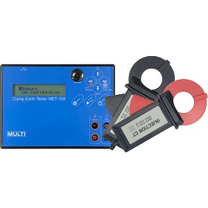
Next clamp-type grounding resistance tester that can connect to a smartphone via Bluetooth and save data on an our cloud server.
FEATURES
・By connecting to a smartphone or tablet via Bluetooth, it is possible to operate and save data at a remote location (MAX around 10 m)・25 kHz fixed surge impedance measurement
・Measurement with the big diameter CT of Φ80 mm (Option)
DOWNLOAD
- Catalog:e-ca_MET-10X.pdf
- Instruction Manual :e-ma-MET-10Xver2.pdf
| Range | Measurement range | Resolution | Accuracy |
| 10 Ω | 0.10~10.00 Ω | 0.01 Ω | 0.10~1.00 Ω:±0.10 Ω 1.00~10.00 Ω:±0.50 Ω |
| 100 Ω | 10.0~100.0 Ω | 0.1 Ω | 10.0~50.0 Ω:±2.0 Ω 50.0~100.0 Ω:±5.0 Ω |
| 1000 Ω | 100.0~500.0 Ω | 0.1 Ω | 100.0~200.0 Ω:±5.0 Ω 200.0~300.0 Ω:±20.0 Ω 300.0~500.0 Ω:±30.0 Ω |
| 500.0~1000 Ω | 1 Ω | 500~800 Ω:±50 Ω 800~1000 Ω:±80 Ω |
| SPECIFICATIONS | |
|---|---|
| Measuring function | Earth Resistance AC Current (Load and Leakage) Surge impedance |
| AC current measurement (23 ℃ ±5 ℃, 80 %RH or less) | Range : 200 mA Measurement range : 0.0~200 mA Resolution : 0.1 mA Accuracy : 3 %rdg ±8 dgt Range : 2000 mA Measurement range : 200~2000 mA Resolution : 1 mA Accuracy : 2 %rdg ±8 dgt Range : 20 A Measurement range : 2.00~20 A Resolution : 0.01 A Accuracy : 2 %rdg ±8 dgt |
| Injection signal | Approx. 160 mVp-p, Auto sweep 3 kHz~200 kHz |
| Memory function | 200 measuring data can be stored and displayed |
| Measuring CT | φ34 mm with 2.5 m lead |
| Injection CT | φ34 mm with 2.5 m lead |
| Measuring time | Earth Resistance:Approx. 30 sec. /1 time Surge impedance:Approx. 1 sec. /1 time |
| A/D Conversion | Dual slope integration mode |
| Over range indication | "OVER" on LCD |
| Data hold indication | "DH" mark on LCD |
| Low battery indication | Battery mark on LCD |
| Sampling | Approx. 2 times/1 sec. for AC current |
| Auto power off function | Approx. 10 min. after the last button operation |
| Withstanding Voltage | AC 3700 V, 1 min. (between CT core and CT handle) |
| Insulation Resistance | More than 100 MΩ by 500 V insulation resistance tester (between CT core and CT handle) |
| Limitation of circuit voltage | Less than 500 V |
| Size and Weight | Main unit : 190(W)×140(H)×42 (D) mm, approx. 450 g Measuring Φ34 mm CT : 90.5(W)×165(H)×38(D) mm, approx. 460 g Measuring Φ80 mm CT : 125(W)×240(H)×40(D) mm, approx. 570 g Injection Φ34 mm CT : 90.5(W)×165(H)×38(D) mm, approx. 440 g Injection Φ80 mm CT : 125(W)×240(H)×40(D) mm, approx. 670 g |
| Storage Temperature | -10 ℃~60 ℃, < 80 %RH (without condensation) |
| Operating Temperature | 0 ℃~40 ℃, < 85 %RH (without condensation) |
| Power supply | AA alkaline battery LR6×4 AC adapter (US type) |
| Power consumption | Approx. 160 mA When battery voltage 6 V (Earth resistance measurement) |
| Accessories | Measuring CT : 1 Injection CT : 1 Carrying case : 1 Subsidiary lead wire : 1 Instruction manual : 1 |
| Option | AC adapter <UNI315-0916> Measuring Φ80 mm CT Injection Φ80 mm CT |
FAQ
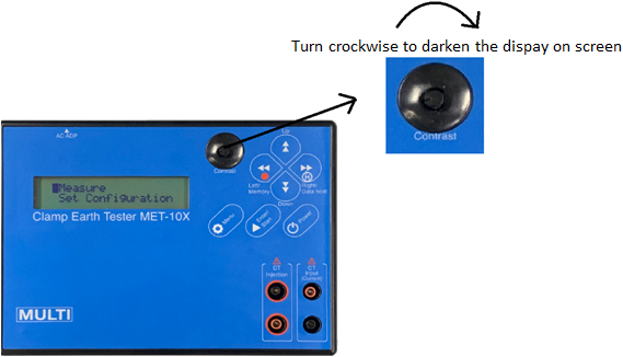
- Pressed the power button however it does not display, is it broken down?
- There is a function that using the dial button of Contrast, the brightness on the display can be adjusted. Turning it to leftmost, please check whether it can be displayed or not because turning it to leftmost, it looks like it can not be displayed.
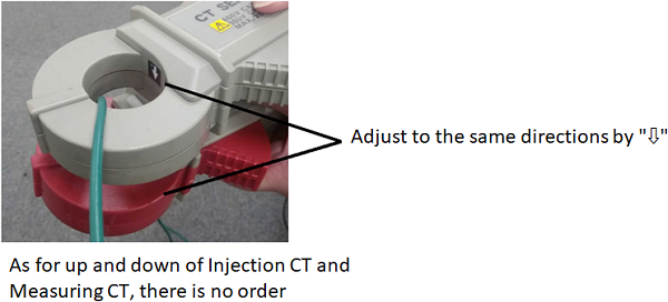
- When clamping Injection CT and Measuring CT, is there the correct direction to clamp or order of things to do?
- Set arrows of Injection CT and Measuring CT to the same direction and clamp. In addition, if arrows of Injection CT and Measuring CT are set to the same direction, any direction is ok and it is ok that you put up which CT to clamp, Injection CT and Measuring CT.
- It displays 0Ω or very lowered values. (or displays "OVER")
- There is possibility that it can not measure with the correct condition. Please check the below items.
・You do not mistake on kind of ground? (May be misunderstanding on single ground and multiple grounding and so on.)
・Isn't it the site that it can not measure? (Please refer to "Is there any site that it is unable to use?")
・Isn't it that the ground wire is floating?
・Check whether Injection CT and Measuring CT are connected to the main body or not.
・Check whether Clamping part is closed perfectly or not.
- Is there any site that it is unable to use?
- MET can not be used on the mesh ground or place that ground wire are integrated in the basement (Display 0, the measured value) and it can not used in the case that there is branch between grounding poles, from the place you clamped because the measuring current will be divided into the grounding pole and branch circuit.
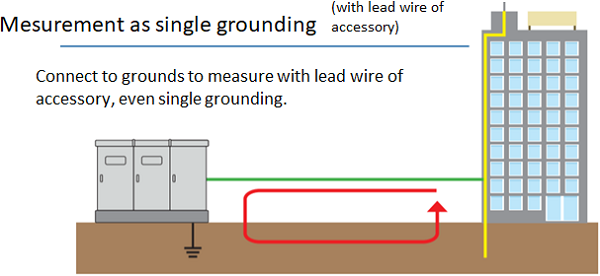
- Is it possible to measure the single ground?
- With auxiliary lead wire, it is possible to measure the single ground by forming lowered enough grounding pole and loop circuit artificially. (Please be noted that resistance values will also be added to the measured values. Use the body such as steel frame of building, as a lowered enough grounding pole.)
- The values measured by MET series is different with the values measured by "Tripolar method?
- It happens that the measured value is different because of different measuring method. Please confirm it when completing inspection.
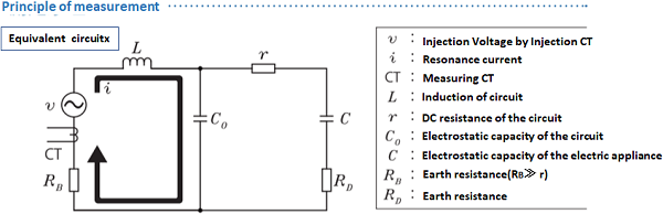
- Please explain about the principle of measurement.
- Inject voltage by Inject CT and calculate the resistance values from detecting the current by Measuring CT that come back, using Ohm's Law.
- How can the auxiliary lead wire, accessory item, be used?
- It can be used for the measurement of the ground resistance on single ground. (Please refer to "Is it possible to measure the single ground?")
- Is it usable on the site during power outage? Or if there is other condition to take measurement, please let me know that.
- During the power outage, it can not measure the resonance phenomenon because of no capacitance C but it can measure, forming the lowered enough grounding pole and loop circuit with the auxiliary lead wire.
- When CT is broken down, is it possible to buy only CT?
- We do not sell only CT because it needs to adjust the accuracy of main body and CT. (matching)